
2 Secondary Coordinate Systems You Should Know
Coordinate systems tell a CNC machine where to position the cutting tool during the program’s execution for any purpose that requires the cutting tool to move.
.jpg;width=70;height=70;mode=crop;format=webp)


Coordinates specified within a CNC program tell a CNC machine where to position the cutting tool during the program’s execution. This could be for the purpose of making the cutting tool approach the workpiece, to make the cutting tool machine surfaces, to retract the axes to the tool changing position or for any other purpose that requires the cutting tool to move.
Coordinate systems, in part, specify the point of origin for each coordinate. The most common coordinate system is the workpiece coordinate system. Its origin is usually along an important workpiece surface in each axis, often called a datum surface. This means coordinates specified in the workpiece coordinate system can be specified from a common and logical point often called the program zero point.


Machining center applications sometimes require the use of more than one workpiece coordinate system. Consider running two or more workpieces on a vertical machining center. Each workpiece will likely have its own workpiece coordinate system. FANUC uses workpiece coordinate system offsets, using G54-G59 to specify which workpiece coordinate system is being used.
There are two other coordinate systems that programmers should know. More importantly, programmers should recognize applications for their use.
Machine coordinate system (specified with G53 on a FANUC CNC)
The origin for the machine coordinate system is the reference position in each axis. The reference position is often very close to where each axis will overtravel in the positive direction. This means that the polarity for coordinates specified in the machine coordinate system will be negative. Consider, for example, this command (for a FANUC CNC):
- G53 X0 Y0 Z0 (Move all axes to their reference positions)
This sends the X-, Y- and Z-axes to their reference position. Rapid mode is automatically selected and used for G53 commands.
Understanding the machine coordinate system is important with certain accessory devices, like pallet changers used on machining centers and programmable tailstocks on turning centers. It is often necessary to move one or more axes to a precise location before the device can be activated, especially when the position is not at the axis’s reference position, but a known distance from it.
Determining this position relative to the workpiece coordinate system origin would require calculations, and would be different with each new job. Say you have a pallet changer being used on a horizontal machining center that requires the X-axis to be at its reference position and the Z-axis to be positioned 5.0 inches from its reference position. This simple (FANUC CNC) command will work every time a pallet change is required:
- G53 X0 X-7.0 (Move axes to pallet change position)
Local coordinate system (specified with G52 on a FANUC CNC)
This coordinate system lets you temporarily shift the origin in the workpiece coordinate system. This (FANUC CNC) command, for instance, shifts the origin by 2.0 inches in the X-axis and 3.0 inches in the Y-axis in the positive direction:
- G52 X2.0 Y3.0
This command by itself does not cause axis motion, but subsequent motion commands will be affected until you reset/cancel the local coordinate system with this command:
- G52 X0 Y0
The local coordinate system is especially helpful when multiple identical features, like pockets on machining centers or grooves on turning centers, must be machined. Combined with a simple subprogram that machines one of the features, this technique simplifies programming, shortens programs and streamlines the program verification process (if one feature is machined properly, they all will be).
Figure 1 shows an example. While the drawing is not dimensioned, you should be able to follow along. In line N040 of the main program, the local coordinate system command temporarily shifts the origin from the lower-left corner of the workpiece in the X- and Y-axes to the lower-left corner of the left-most pocket. Line N050 commands the subprogram to be executed, which machines one pocket. Line N060 then shifts the coordinate system to the lower-left corner of the second pocket. Line N070 commands the subprogram again, and the second pocket is machined. This is repeated two more times. Note that Line N120 resets/cancels the local coordinate system.
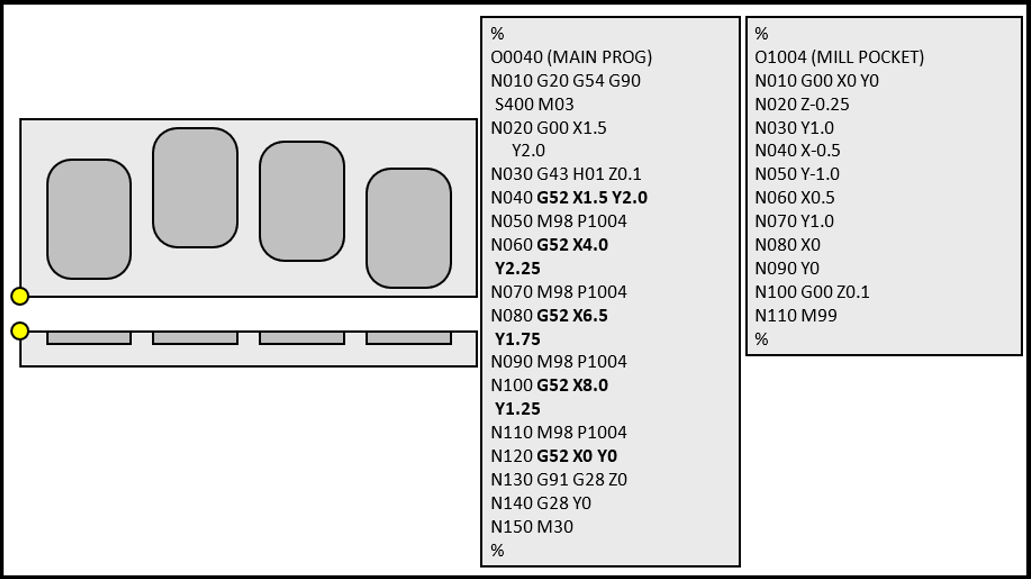
Figure 1: Local coordinate system subprogram example. Source: Mike Lynch


Related Content

How to Mitigate Chatter to Boost Machining Rates
There are usually better solutions to chatter than just reducing the feed rate. Through vibration analysis, the chatter problem can be solved, enabling much higher metal removal rates, better quality and longer tool life.
Read More
Can ChatGPT Create Usable G-Code Programs?
Since its debut in late 2022, ChatGPT has been used in many situations, from writing stories to writing code, including G-code. But is it useful to shops? We asked a CAM expert for his thoughts.
Read More
Fearless Five-Axis Programming Fosters Shop Growth
Reinvestment in automation has spurred KCS Advanced Machining Service’s growth from prototyping to low-and mid-volume parts. The key to its success? A young staff of talented programmers.
Read More
Automating Part Programming Cuts the Time to Engaging Work
CAM Assist cuts repetition from part programming — early users say it could be a useful tool for training new programmers.
Read MoreRead Next

IMTS 2024: Trends & Takeaways From the Modern Machine Shop Editorial Team
The Modern Machine Shop editorial team highlights their takeaways from IMTS 2024 in a video recap.
Read More
The Future of High Feed Milling in Modern Manufacturing
Achieve higher metal removal rates and enhanced predictability with ISCAR’s advanced high-feed milling tools — optimized for today’s competitive global market.
Read More
Increasing Productivity with Digitalization and AI
Job shops are implementing automation and digitalization into workflows to eliminate set up time and increase repeatability in production.
Read More